|
Prior to fully painting the frame of our Japanese tent, all the parts were labelled in English, but as a replica of a SAMURAI tent, this definitely wasn't quite right for the finished AKUNOYA! And so, these labels have now been translated in to Japanese script, and this page deals with that translation.
Four things:
-
Do not panic, you do not need to learn the characters if you do not wish to, just learn to match up the pretty symbols in their sets.
-
During our period ileteracy was riefe, so an inability to read or write in Japanese is not a true handicap when taking on the role of a low class warrior.
-
If you do want to learn to read the script for use with the tent, you only need to master the first five KANJI numbers, 1, 2, 3, 4 and 5. You do not even need to learn how to pronounce them.
-
I have included the details for the digits 6 ~ 10 as well, plus a pronunciation guide for all of the numbers, just in case.
The Original Labelling Scheme
The tent frame comprises 64 individual parts. It is made up of 5 truss' originally labelled A, B, C, D and E, which prefixed a number identifying each part. The two end truss' (A and E) have 3 legs each, and the other three (B, C and D) only have 2 legs each. Between each truss are three horizontal roof beams, labelled with two letters identifying to which gap they belong, and a number identifying their correct position. See the following two diagrams. The first is an end view of Truss A (the entrance), and the second is a side view of Truss A and Truss B, with the intervening roof beams, viewed from their right hand side :


The original parts range is as follows:
-
A1 ~ A11 Truss A, note that A11 was the middle leg.
-
AB1, AB2 & AB3 The horizontal roof beams.
-
B1 ~ B10 Truss B
-
BC1, BC2 & BC3 The horizontal roof beams.
-
C1 ~ C10 Truss C
-
CD1, CD2 & CD3 The horizontal roof beams.
-
D1 ~ D10 Truss D
-
DE1, DE2 & DE3 The horizontal roof beams.
-
E1 ~ E11 Truss E, note that E11 was the middle leg.
The Japanese Labelling Scheme
Listed in the first table are the five KANJI numbers which form the labels that will help us when we are putting up the wooden frame of our Japanese tent. They are used thus:
Each label contains two digits, and defines each element as part of a set. The parts are sufficiently different from one another not to require any additional numbering other than Truss and set, however in this document each element has also been assigned a Part No. for future reference:
-
The first digit identifies the truss, and thus the original labels of A, B, C, D, and E have been replaced by 1, 2, 3, 4, and 5 respectively.
-
The second digit identifies the set to which the part belongs. Each set contains one or two joints and one leg each, as follows:
-
Set 1: the right hand side of the tent frame, containing one joint and one leg.
-
Set 2: the centre line of the tent frame, containing two joints (one upper, one lower), and one leg.
-
Set 3: the left hand side of the tent frame, containing one joint and one leg.
-
All horizontal and sloping roof beams within a truss are labelled at one end with the identity of the outside joint to which they attach.
-
The horizontal roof beams that link one truss to another, are labelled at one end with the identity of the set to which they are initially attached, followed by the identity of the set in the next truss. This is done to distinguish these from the similar horizontal beams within a truss.
Here is an example of a complete Japanese label, the middle leg at the rear end of the tent which was originally labelled as E11, is now inscribed vertically as 5 2. The 5 is the truss number at the back of the tent, and the 2 indicates that the leg belongs to the centre group.
FYI this would be said as "GO SAN", literally "five three". And no that isn't how you say 53 BTW.
The table below has images of the numbers in what is called KAISHO TAI style, which was used for carving KANJI in to wood during our period. Each character has been carved as though it was in its own personal square. This may seem wasteful of space, but it is vital to have done this otherwise for example three number ones, or a number one and a number 2, could be potentialy mistaken for a number three.
Note that all labels are written vertically in classic Japanese fashion, even on the horizontal roof beams, as that is the way they will be read when picked up for sorting and assembly.
All the centre joints could, if not labelled correctly be installed the wrong way around. Therefore each is labelled on its front face, that is on the side towards you when viewed from the tent's entrance.
Click the individual KANJI images to view a larger edition, then use your back button to return to this page.

1
"ee-che"
SPACE
SPACE
|
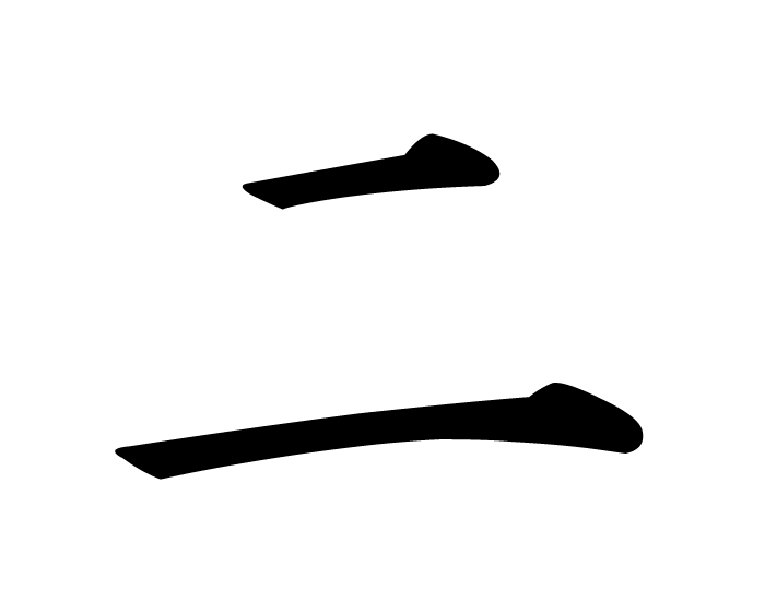
2
"knee"
SPACE
SPACE
|
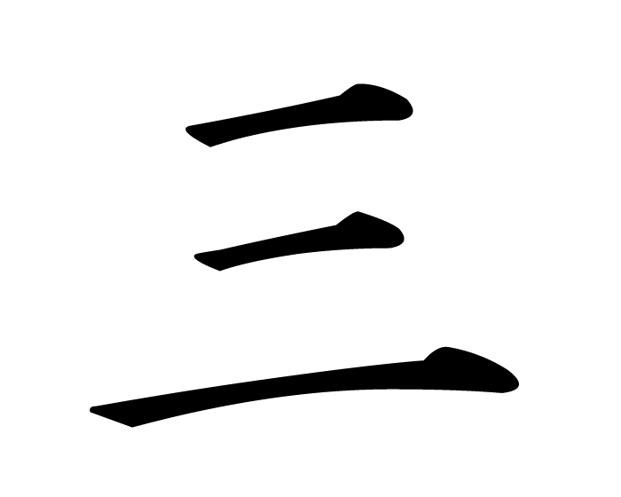
3
"sah'n"
SPACE
SPACE
|

4
"yoh'n"
or
"she"
|
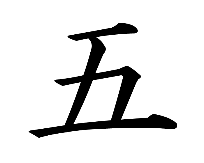
5
"goh"
SPACE
SPACE
|
|---|

6
"roh-koo"
SPACE
SPACE
|
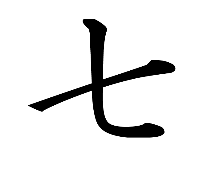
7
"she-che"
or
"nah-nah"
|
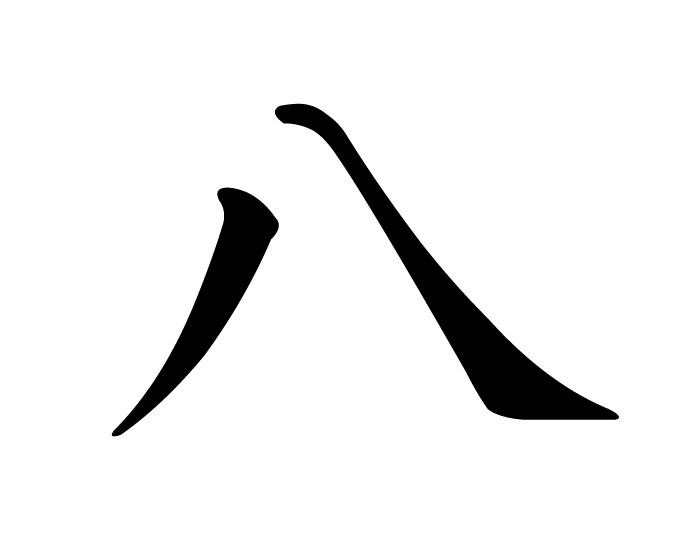
8
"hah-che"
SPACE
SPACE
|
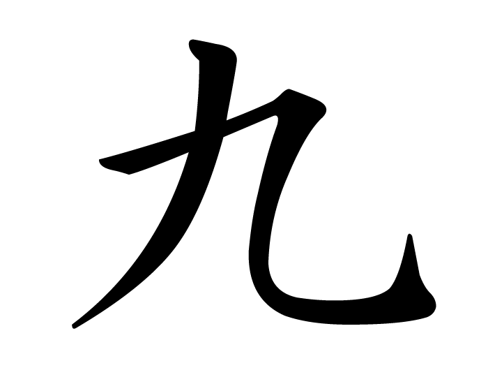
9
"koo"
or
"queue"
|
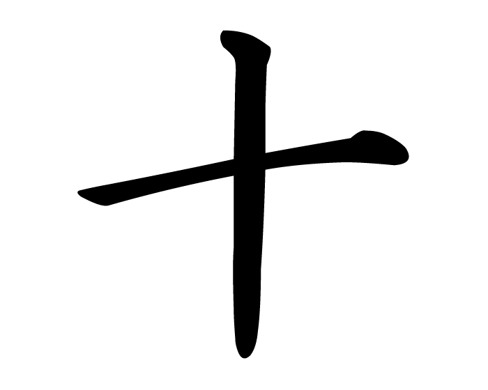
10
"jew"
SPACE
SPACE
|
|---|
The Full Parts List
The positioning descriptions used below presume that you are looking towards the narrow entrance end of the tent, that is Truss 1, and the convention is that all the parts are identified starting with the truss' front to back, then the joint groups within each truss, 'reading' them from top to bottom, right to left in Japanese fashion.
To reduce the amount of carving required, the parts within a set are not further identified by another number. Once each set is grouped together it will be obvious which part goes where. For example the four parts of the centre group of trus 1 are all labelled as group "12", the final piece being the roof beam which is labelled in full as "1222". In the diagrams of Truss A above, they are labelled top to bottom; A2, AB2, A6, and A11 respectively.
This table contains a full list of all the parts of the tent frame with their Japanese characters in a standard computerised font to try and save space.
The original designation is included in brackets for those requiring to refer to the design diagrams, and this is followed by a Part No., that only appears in this document as a reference tool.
|
一
|
Truss 1 (Front Entrance)
|
|---|
|
一
Group 1
|
|---|
一
一
|
Truss 1, Right Hand, Corner Joint. (A8) Part No. 01
1
1
|
|---|
一
一
|
Truss 1, Right Hand, Corner Leg. (A10) Part No. 02
1
1
|
|---|
一
一
|
Truss 1, Right Hand, Sloping Roof Beam. (A3) Part No. 03
Marked at the socket end of the beam.
1
1
|
|---|
一
一
|
Truss 1, Right Hand, Horizontal Beam. (A7) Part No. 04
Marked at the outside socket end of the beam.
1
1
|
|---|
一
一
二
一
|
Trus 1, Right Hand, Horizontal Roof Beam. (AB3) Part No. 05
1
1
2
1
|
|---|
|
二
Group 2
|
|---|
一
二
|
Truss 1, Centre, Upper Joint. (A2) Part No. 06
1
2
|
|---|
一
二
|
Truss 1, Centre, Lower Joint. (A6) Part No. 07
1
2
|
|---|
一
二
|
Truss 1, Centre, Leg. (A11) Part No. 08
1
2
|
|---|
一
二
二
二
|
Truss 1, Centre, Horizontal Roof Beam. (AB2) Part No. 09
1
2
2
2
|
|---|
|
三
Group 3
|
|---|
一
三
|
Truss 1, Left Hand, Sloping Roof Beam. (A4) Part No. 10
Marked at the socket end of the beam.
1
3
|
|---|
一
三
|
Truss 1, Left Hand, Horizontal Beam. (A5) Part No. 11
Marked at the outside socket end of the beam.
1
3
|
|---|
一
三
|
Truss 1, Left Hand, Corner Joint. (A4) Part No. 12
1
3
|
|---|
一
三
|
Truss 1, Left Hand, Corner Leg (A9). Part No. 13
1
3
|
|---|
一
三
二
三
|
Truss 1, Left Hand, Horizontal Roof Beam. (AB1) Part No. 14
1
3
2
3
|
|---|
|
二
|
Truss 2
|
|---|
|
一
Group 1
|
|---|
二
一
|
Truss 2, Right Hand, Corner Joint. (B8) Part No. 15
2
1
|
|---|
二
一
|
Truss 2, Right Hand, Corner Leg. (B10) Part No. 16
2
1
|
|---|
二
一
|
Truss 2, Right Hand, Sloping Roof Beam. (B3) Part No. 17
Marked at the socket end of the beam.
2
1
|
|---|
二
一
|
Truss 2, Right Hand, Horizontal Beam. (B7) Part No. 18
Marked at the outside socket end of the beam.
2
1
|
|---|
二
一
三
一
|
Trus 2, Right Hand, Horizontal Roof Beam. (BC3) Part No. 19
2
1
3
1
|
|---|
|
二
Group 2
|
|---|
二
二
|
Truss 2, Centre, Upper Joint. (B2) Part No. 20
2
2
|
|---|
二
二
|
Truss 2, Centre, Lower Joint. (B6) Part No. 21
2
2
|
|---|
二
二
三
二
|
Truss 2, Centre, Horizontal Roof Beam. (BC2) Part No. 22
2
2
3
2
|
|---|
|
三
Group 3
|
|---|
二
三
|
Truss 2, Left Hand, Sloping Roof Beam. (B4) Part No. 23
Marked at the socket end of the beam.
2
3
|
|---|
二
三
|
Truss 2, Left Hand, Horizontal Beam. (B5) Part No. 24
Marked at the outside socket end of the beam.
2
3
|
|---|
二
三
|
Truss 2, Left Hand, Corner Joint. (B4) Part No. 25
2
3
|
|---|
二
三
|
Truss 2, Left Hand, Corner Leg. (B9) Part No. 26
2
3
|
|---|
二
三
三
三
|
Truss 2, Left Hand, Horizontal Roof Beam. (BC1) Part No. 27
2
3
3
3
|
|---|
|
三
|
Truss 3 (Middle Truss)
|
|---|
|
一
Group 1
|
|---|
三
一
|
Truss 3, Right Hand, Corner Joint. (C8) Part No. 28
3
1
|
|---|
三
一
|
Truss 3, Right Hand, Corner Leg. (C10) Part No. 29
3
1
|
|---|
三
一
|
Truss 3, Right Hand, Sloping Roof Beam. (C3) Part No. 30
Marked at the socket end of the beam.
3
1
|
|---|
三
一
|
Truss 3, Right Hand, Horizontal Beam. (C7) Part No. 31
Marked at the outside socket end of the beam.
3
1
|
|---|
三
一
四
一
|
Trus 3, Right Hand, Horizontal Roof Beam. (CD3) Part No. 32
3
1
4
1
|
|---|
|
二
Group 2
|
|---|
三
二
|
Truss 3, Centre, Upper Joint. (C2) Part No. 33
3
2
|
|---|
三
二
|
Truss 3, Centre, Lower Joint. (C6) Part No. 34
3
2
|
|---|
三
二
四
二
|
Truss 3, Centre, Horizontal Roof Beam. (CD2) Part No. 35
3
2
4
2
|
|---|
|
三
Group 3
|
|---|
三
三
|
Truss 3, Left Hand, Sloping Roof Beam. (C4) Part No. 36
Marked at the socket end of the beam.
3
3
|
|---|
三
三
|
Truss 3, Left Hand, Horizontal Beam. (C5) Part No. 37
Marked at the outside socket end of the beam.
3
3
|
|---|
三
三
|
Truss 3, Left Hand, Corner Joint. (C4) Part No. 38
3
3
|
|---|
三
三
|
Truss 3, Left Hand, Corner Leg. (C9) Part No. 39
3
3
|
|---|
三
三
四
三
|
Truss 3, Left Hand, Horizontal Roof Beam. (CD1) Part No. 40
3
3
4
3
|
|---|
|
四
|
Truss 4
|
|---|
|
一
Group 1
|
|---|
四
一
|
Truss 4, Right Hand, Corner Joint. (D8) Part No. 41
4
1
|
|---|
四
一
|
Truss 4, Right Hand, Corner Leg. (D10) Part No. 42
4
1
|
|---|
四
一
|
Truss 4, Right Hand, Sloping Roof Beam. (D3) Part No. 43
Marked at the socket end of the beam.
4
1
|
|---|
四
一
|
Truss 4, Right Hand, Horizontal Beam. (D7) Part No. 44
Marked at the outside socket end of the beam.
4
1
|
|---|
四
一
五
一
|
Trus 4, Right Hand, Horizontal Roof Beam. (DE3) Part No. 45
4
1
5
1
|
|---|
|
二
Group 2
|
|---|
四
二
|
Truss 4, Centre, Upper Joint. (D2) Part No. 46
4
2
|
|---|
四
二
|
Truss 4, Centre, Lower Joint. (D6) Part No. 47
4
2
|
|---|
四
二
五
二
|
Truss 4, Centre, Horizontal Roof Beam. (DE2) Part No. 48
4
2
5
2
|
|---|
|
三
Group 3
|
|---|
四
三
|
Truss 4, Left Hand, Sloping Roof Beam. (D4) Part No. 49
Marked at the socket end of the beam.
4
3
|
|---|
四
三
|
Truss 4, Left Hand, Horizontal Beam. (D5) Part No. 50
Marked at the outside socket end of the beam.
4
3
|
|---|
四
三
|
Truss 4, Left Hand, Corner Joint. (D4) Part No. 51
4
3
|
|---|
四
三
|
Truss 4, Left Hand, Corner Leg (D9). Part No. 52
4
3
|
|---|
四
三
五
三
|
Truss 4, Left Hand, Horizontal Roof Beam. (DE1) Part No. 53
4
3
5
3
|
|---|
|
五
|
Truss 5 (Rear Entrance)
|
|---|
|
一
Group 1
|
|---|
五
一
|
Truss 5, Right Hand, Corner Joint. (E8) Part No. 54
5
1
|
|---|
五
一
|
Truss 5, Right Hand, Corner Leg. (E10) Part No. 55
5
1
|
|---|
五
一
|
Truss 2, Right Hand, Sloping Roof Beam. (E3) Part No. 56
Marked at the socket end of the beam.
5
1
|
|---|
五
一
|
Truss 5, Right Hand, Horizontal Beam. (E7) Part No. 57
Marked at the outside socket end of the beam.
5
1
|
|---|
|
二
Group 2
|
|---|
五
二
|
Truss 2, Centre, Upper Joint. (E2) Part No. 58
5
2
|
|---|
五
二
|
Truss 5, Centre, Lower Joint. (E6) Part No. 59
5
2
|
|---|
五
二
|
Truss 5, Centre, Leg. (E11) Part No. 60
5
2
|
|---|
|
三
Group 3
|
|---|
五
三
|
Truss 5, Left Hand, Sloping Roof Beam. (E4) Part No. 61
Marked at the socket end of the beam.
5
3
|
|---|
五
三
|
Truss 5, Left Hand, Horizontal Beam. (E5) Part No. 62
Marked at the outside socket end of the beam.
5
3
|
|---|
五
三
|
Truss 5, Left Hand, Corner Joint. (E4) Part No. 63
5
3
|
|---|
五
三
|
Truss 5, Left Hand, Corner Leg. (E9) Part No. 64
5
3
|
|---|
|
